10G Ethernet 64b/66b Encoding
Bit encoding is an art unto itself, where there`s plenty of different encoding schemes to choose from. There`s 8b/10b encoding of PCIexpress Version 2, the 128b/130b encoding of PCIExpress Version 3, 64b/67b of interlaken and of course stock 64b/66b encoding used in all 10G, 40G and 100G ethernet protocols.
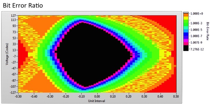
what is a bit, is in the eye of the beholder
So whats the point of yet another encoding scheme? we`ve already got XGMII/XAUI/RXAUI which are fairly sane protocols. If you get into into hardware design you realize the development cost to get two chips to talk to each other in a reliable way at fastest data rates available is hardly trivial, we`re talking way beyond 10`s of millions of dollars in research & development. The protocols by them self take several years for all parties to agree on so it makes sense for the semiconductor industry as a whole to standardize alot of these components. 64b66b encoding is one of these industry standards that strangely enough.. encodes 64bits worth of data with the intent of being sent down a high speed serial link. Currently the serial links of standard Ethernet are fixed at 10.3125Ghz and 25.78125Ghz and it will probably stay that way for at least the next 5 years, until 400G ethernet starts to gain wide spread adoption.
But whats with these funky frequency rates ? 10G ethernet should be exactly 10.000GHz, and not 10.3125Ghz? Well, that's kind of true, but kind of not. 10G ethernet is 10Ghz of serialized data payload which does not include the control payload bandwidth. If we do the math of 2b (of control) / 64b (of data) = 66b encoding = 0.03125 a number that looks quite familiar. It means the encoding overhead is 3.125% of the data rate, which also means if we run the serial link at exactly 10.00Ghz then 3.125% of that 10Ghz bandwidth will be dedicated to control logic leaving 10Ghz - 0.3125Ghz = 9.6875Ghz remains for data. That of course means 10G ethernet is no longer 10Gbit of payload so.. what did the designers do ? what all modders do, they overclocked that shit! Now its hard to imagine an uber crazy nitro-watercooled network 100Ghz transceiver's gaining much traction in the market, but what did gain acceptance is a slight 3.125% overclocking of the serial link to make the final link speed 10.3125Ghz with 0.3125Ghz for control and a full 10.0Ghz of bandwidth for data.
So now we have a 10.3125Ghz serialized data link, and need to push something down the wire. Remember this is just a serialized stream of bits and one important electrical characteristic you need is, a stream of varying bits to keep the link stable and error free. This is whats known as DC Balance, as the 1's are encoded with high voltage, and 0's negative voltage which means if your serialized data is this massive string of 0's the average voltage on the link over a time will be negative, and similarly if your sending a string of 1's the average voltage will be positive. This is a bad thing, ideally you want the mean voltage to be 0 Volts meaning half of the bits should be 1's and the other half should be 0's aka "Balance". This is largely the responsibility of the scrambler but the 64b66b encoder helps this by forcing the control bits to be binary 01 or binary 10. Thus even if the payload is all 0's or all 1's the serialized output will always go low(0) or high(1) once for every 66bits of transmission.
...Enough of the theory, whats the format ? As always its very simple. the extra 2cups^H^H^H I mean extra 2bits for every 64bits of data indicates if the payload is a control data or payload data.
| 2bits (Sync) | 64bits (Block Payload) |
| 01b | 64b Data Payload |
| 10b | 64b Control Payload |
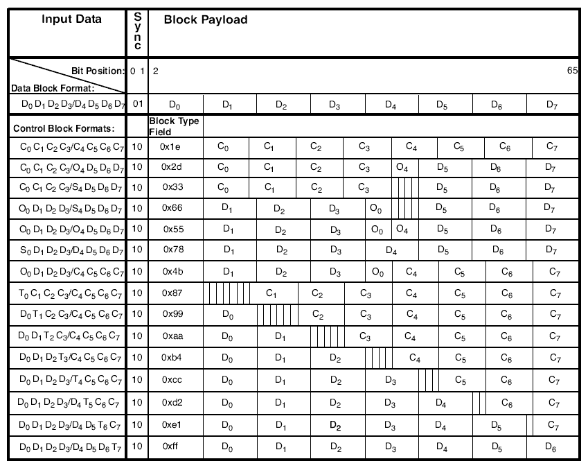
Which looks remarkably similar to how the XGMII encoding looks, but its not. Remember the XGMII encoding is 1bit of control (0b -> data, 1b -> control) for every 8bits of data. Making it an 8b/9b encoding. If we scale that to 64b worth of data it becomes 64b/72b encoding with an overhead of 8b (of control) / 64b (of data) = 12.5% overhead. Which quite frankly sucks major ass. What the designers realized is there`s actually very few control words relative to the entire 64bit value control space so they chopped off 1 bit of each control data byte, enabling them to pack the same information as XGMII but in a much more compact and efficient way. The encoding table is below.

Which looks like something you scare little (and big) kids (and adults) with. Will admit its a bit wtf when you first look at this, but once you understand the table, then its actually quite simple. Lets dig.
First, the easy part:

Which means when control sync bits (2nd column) is 01, then the 64bits of payload, is 8 bytes (D0, D1, ... D7) of data. Nothing surprising here, its effectively a passthrough operation for data blocks.
Next up is.

When the control sync bits (2nd col) are 10b then its a control block format. This is where it gets a little bit tricky. You`ll notice the "Block Type Field" shares the same vertical line in the table as the D0 payload fields above. This means The "Block Type Field" is 8bits, just as the D0 data field is also 8bits. Look at the whole table until that makes sense. But C0, C1, ... C7 are not aligned with the Dx vertical lines, and are in fact 7bits each. So if we add all the bit`s up, 8bits (Block Type Field) + 7bits (C0) + 7bits (C1) + 7bits (C2) + 7bits (C3) + 7bits (C4) + 7bits (C5) + 7bits (C6) + 7bits (C7) = 8 + 8*7 = magical 64bits.
Ok, so the Cx fields are 7bits each, cool. Going back to the XGMII specification, remember the control words for idle is 0x07? Notice how only the 3 LSB bits set? as such we can easily encode the number 0x07 into 7bits of data, by dropping the 8th bit! Which makes the XGMII idle sequence converted into 64b66b look like:
| Type | 64b XGMII Control bit | 64b XGMII Data Byte | 64b66b Control bit | 64b66b Data Byte |
| Idle Cycle | 11111111b | 0x07070707_07070707 | 10b | 1e0e1c3870e1c387 |
Whats with the weird ass 64b66b Data byte ?
1e0e1c3870e1c387
An easier way to understand it is the following C code, that outputs the same number.
v = 0;
v |= (0x1eULL << 7*8); // Block Field Type
v |= (0x07ULL << 7*7); // C0
v |= (0x07ULL << 7*6); // C1
v |= (0x07ULL << 7*5); // C2
v |= (0x07ULL << 7*4); // C3
v |= (0x07ULL << 7*3); // C4
v |= (0x07ULL << 7*2); // C5
v |= (0x07ULL << 7*1); // C6
v |= (0x07ULL << 7*0); // C7

printf("%016llx\n", v); // 0x1e0e1c3870e1c387
Which takes care of the idle control words. How about the start and end of frame control words? From the previous XGMII section we know 0xFB -> start of frame and 0xFD -> end of frame, but we have a problem...it uses all 8 bits... it will not fit into 7bits... and we`re doomed. Not quite. Start / End of frame control data are encoded implicitly which takes us to the next row.

Notice how the first table column is "S0,D1,D2,D3,...D7" ? It means S0 = Start of Frame, D1 = Data byte 1, D2 = Data byte 2, etc etc. So our trusty 0xFB XGMII control word is actually encoded into the "BlockTypeField" (first 8bits of data) using the value 0x78. Kinda cool and nifty I think, and certainly some smarty pants bit hackers were involved designing the protocols. One thing to remember is for 10G the start of frame always starts in lane 0, or lane 4, thus you don't have to worry about Start-of-Frame markers at all byte positions. Whats even better is at 40G & 100G start of frame always starts in lane 0.
Lets update the conversion table to the following.
| Type | 64b XGMII Control | 64b XGMII Data | 64b66b Control | 64b66b Data |
| Idle Cycle | 11111111b | 0x07070707_07070707 | 10b | 1e0e1c3870e1c387 |
| Start of Frame | 10000000b | 0xFB555555_5555555D | 10b | 78555555_5555555D |
And finally the End-of-Frame markers are encoded as follows.

Where the 1st column is "T0,C1,C2,C3,C4,C5,C6,C7", meaning T0 = Terminate or End of Frame or our friend 0xFD, with Cx the usual Control words. As with Start of frame we don't need to explicitly encode the 0xFD XGMII control code, as its implied based on which table entry is selected. Similarly for the 2nd column D0,T1,C2,C3,C4,C5,C6,C7 means there`s 8bits of data, then the frame terminates, and so on for the other ending byte lane positions.
Our final XGMII to 64b66b conversion table looks like
(where zz = 8 bits of payload data)
| Type | 64b XGMII Control | 64b XGMII Data | 64b66b Control | 64b66b Data |
| Idle Cycle | 11111111b | 0x07070707_07070707 | 10b | 1e0e1c3870e1c387 |
| Start of Frame | 10000000b | 0xFB555555_5555555D | 10b | 78555555_5555555D |
| End of Frame L0 | 11111111b | 0xFD070707_07070707 | 10b | 870e1c3870e1c387 |
| End of Frame L1 | 01111111b | 0xzzFD0707_07070707 | 10b | 99zz1c3870e1c387 |
| End of Frame L2 | 00111111b | 0xzzzzFD07_07070707 | 10b | AAzzzz3870e1c387 |
| End of Frame L3 | 00011111b | 0xzzzzzzFD_07070707 | 10b | B4zzzzzz70e1c387 |
| End of Frame L4 | 00001111b | 0xzzzzzzzz_FD070707 | 10b | CCzzzzzzzze1c387 |
| End of Frame L5 | 00000111b | 0xzzzzzzzz_zzFD0707 | 10b | D2zzzzzzzzzzc387 |
| End of Frame L6 | 00000011b | 0xzzzzzzzz_zzzzFD07 | 10b | E1zzzzzzzzzzzz87 |
| End of Frame L7 | 00000001b | 0xzzzzzzzz_zzzzzzFD | 10b | FFzzzzzzzzzzzzzz |
Hopefully you`ve gotten a good overview of how XGMII is converted into 64b/66b based encoding scheme and why such a scheme is used (its more efficient!). When your building hardware its alot messier and we`ve completely left out discussion of error codes, ordered sets and some of the other random things in the protocol. The above represents the core basics of how packets are encoded into a 66bit format, and consult the (painfully verbose) specification if you need more err... detail.
After 64b/66b encoding there`s the "Scrambler" which as the name implies turns the bits into scrambled eggs. We`ll detail the correct pan temperature and spatula techniques for medium well done scrambled bits in the next article.


